Product Advisories
Safety/ Maintenance
Acrylic Window Aging – Maintenance & Inspections
We at Perry Baromedical would like to thank you for your purchase of a Perry Baromedical Hyperbaric Chamber. Whether you’re a first time customer or a long-term member of the Perry family, we truly hope your facility is enjoying a successful operating program and that you have been able to treat your patients in a manner that has helped them through difficult recoveries.
As the end-user of a PVHO chamber (Pressure Vessel for Human Occupancy), and according to the requirements contained within the Operator’s Manual, ASME/PVHO-2 (Clause 1-2.1, Clause 1-6.1), NFPA 99 (National Fire Protection Association Clause 14.3.1.3.2), and the FDA (US Food and Drug Administration – implicit operators responsibilities pursuant to the manufacturers statement of specified servicing under FDA 21CFR Part 820, Subpart N, Section 820.200), your facility is responsible for developing and implementing a maintenance program that will specifically address and satisfy the requirements for the proper inspection of the acrylic window (in addition to the general chamber maintenance requirements). The purpose of this memo is to alert you of these and additional requirements specifically in regards to the acrylic window as the window nears the end of the 10-year design life. It is strongly suggested that you obtain copies of the above referenced documents and read them thoroughly.
These controlling standards, and in particular, PVHO-2, Section 2 (Viewports), Clause 2-4.1, calls for (1) an operational acrylic window inspection based on daily usage, and (2) a more comprehensive maintenance inspection based on design life. Prior to end of design life, in addition to daily inspections, the acrylic window would also be inspected annually, based on the maintenance schedule listed in the Operators Manual. As the acrylic window reaches 10 years of age (or 10,000 cycles, whichever comes first), the inspection requirements become much more stringent and expand to include the need for additional specific documentation. The need and frequency of this inspection schedule is outlined in PVHO- 2, Clause 2-4.3, and is specified at a maximum interval of 24 months after the end of the design life (PVHO-2, Table 2- 4.3-1).
Under normal conditions a 10-year inspection results in a satisfactory review and the chamber is certified to remain in service for an additional (1) year period, with a scheduled re-inspection each year thereafter for a total possible life span of 20 years (or 20,000 cycles, whichever comes first). However it’s important to know that acrylics do age and eventually require replacement. And because of the costs involved, knowing this well before you face the need to do such a replacement will assist you in accurately costing your treatment profiles over the long term.
Please keep in mind that at any time during the annual inspection process (prior to end of design life), if a determination is made that the acrylic has failed the (above referenced) PVHO requirements, and cannot be repaired, or it is in need of replacement based on the applicable standards, the inspecting firm is required to red tag the machine and prohibit its continued use for human treatments. Fortunately, outside of cases of specific trauma to the acrylic window, the aging process is usually gradual and windows can be monitored monthly or quarterly should an anomaly be found during an inspection.
We realize that this inspection and possible “red tag” may severely impact your facilities operating capabilities, but the first priority is patient safety and the requirements under which these devices are built, manufactured, and maintained.
Should you like additional information on the requirements of the referenced code specifications, information on possible inspection programs, or just wish to discuss the general aspects of the chamber servicing requirements, please contact either Perry Baromedical’s Engineering
or Customer Service departments at your earliest convenience.
Safety/ performance
The SIGMA Series Monoplace chamber is intended to be used by prescription only by trained personnel.
The following are general safety requirements regarding chamber operation, the operator of the device and patient safety:
SAFETY: CHAMBER SAFETY
The SIGMA Series monoplace chamber is safe to operate when used as directed, however, the increased pressure inside the chamber, and use of 100% oxygen, requires that the Owner/User take the time to fully understand the operational and functional aspects of the system, including any added cautions associated with operation of the system as a pressure vessel. The increased pressure and the use of 100% oxygen mandate that the Owner/User understand the risks involved. The service requirements and maintenance schedules provided to the owner/user are intended to provide the guidance and instructions needed to maintain the chamber within operational specifications. Perry Baromedical requires that service be performed by suitably trained technicians, who have demonstrated proficiency with the system. This is necessary to mitigate risks associated with the system and assure the Owner/User that the system is maintained in proper working order.
PERSONNEL
All personnel who will operate the hyperbaric chamber should be thoroughly trained in its use and have a good working knowledge of hyperbaric oxygen therapy in general. The selection of competent and experienced personnel is critical to safe usage of hyperbaric chamber systems. The physician in charge should be trained and proficient in the application of hyperbaric oxygen treatment.
PATIENT SAFETY
The user organization should develop and follow its own operating safety procedures, consistent with good medical practice.
Product Advisory & Label Performance
PERFORMANCE
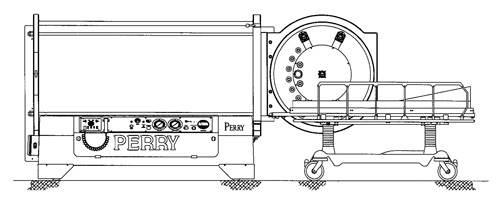
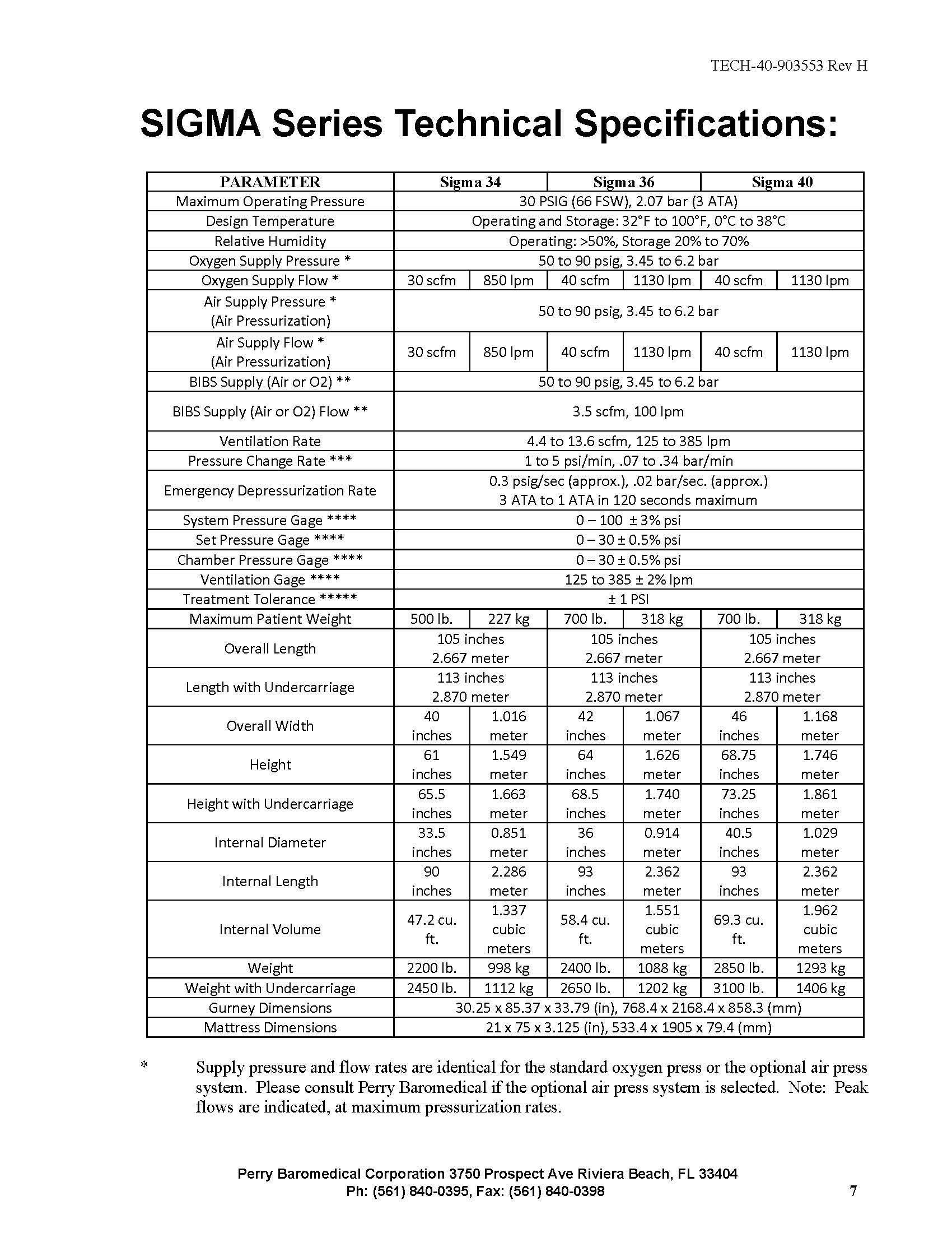
The SIGMA Series Monoplace Hyperbaric Systems provide HBOT hyperbaric oxygen therapy for a single patient with maximum operational pressures of 3 ATA or 30 psig in conformance with applicable IEC 60601-1, NFPA 99, and FDA 21CFR, Chapter 1, Part 820 requirements. The pressure vessel is designed in accordance with applicable ASME & PVHO design codes. The standard system is pressurized with USP Medical Grade Oxygen and pressurization with breathing air is possible using a wall mounted air/oxygen select valve manifold assembly.
The SIGMA Series systems are equipped with an adjustable height patient gurney stretcher system to provide patient entrance into and out of the chamber. The stretcher gurney assembly mates with the chamber and locks into position. Once the gurney is locked, the patient may be rolled into and out of the chamber on the stretcher. Once the door is closed and latched a safety gas interlock allows flow of oxygen and chamber pressurization. A second interlock prevents the door from being opened while the vessel is pressurized.
An operator control panel is provided equipped with the necessary gauges, indicators, and controls necessary for the safe operation of the system. Controls consist of totally pneumatic components, and include adjustable pressurization, depressurization, and ventilation. A 50-90 psig oxygen source is required for standard operation. Features are described below.
The SIGMA chamber system is equipped with a voice communication system consisting of an externally mounted control module and an internally mounted speaker / microphone. An auxiliary input connection is provided to accept an audio input from a radio or TV for patient entertainment.
Standard features:
- Automatic pressurization and depressurization after rates are set.
- Automatic ventilation of the chamber with adjustable rate control and rate meter on the control panel.
- Chamber penetrations providing capability to connect EEG / ECG patient monitoring.
- Chamber penetrations to accept connections for intravenous medications during treatment.
- Gurney / stretcher which locks to chamber for safety during patient transfer.
- Battery backup for continued chamber communications in the event of power outage.
- Pneumatic control only requiring a compressed gas source.
- Left / right door and panel configuration per order.
Controls and instrumentation:
- SUPPLY PRESSURE Gauge – This gauge indicates facility gas system pressure being supplied to the chamber gas control and pressurization circuit.
- SYSTEM “ON / OFF” Switch – This switch activates the gas control system to pressurize the chamber. It will not activate the control system unless the control system interlock switch is activated. This interlock switch is fitted to the chamber below the door, and is activated only when the door is completely closed and latched. This prevents operation of the chamber if the door is open.
- OXYGEN SUPPLY “ON” Indicator – This indicator indicates when the gas supply is present and oxygen is being supplied to the chamber.
- SET PRESSURE Control Knob – This regulator allows adjustment of the desired chamber treatment pressure. To pressurize the chamber, the set pressure is adjusted to the desired pressure. To depressurize the chamber, the set pressure control is adjusted back to zero.
- SET PRESSURE Gauge – This gauge displays the set pressure as adjusted by the set pressure control knob.
- RATE SET Control Knob – This regulator is adjusted to the desired rate of pressurization or depressurization, within an approximate range of 1 to 5 psi/min (.07 to .34 bar/min).
- CHAMBER PRESSURE Gauge – This gauge displays the actual pressure of the chamber.
- EXHAUST BY-PASS Control – (emergency depressurization) – This is a momentary acting push-button. When the push-button is depressed and held, the chamber is depressurized rapidly, at a preset rate. The system ON/OFF switch must be in the OFF position for the button to operate. The primary use of this control is for exhausting the chamber in an emergency. It may also be used to accelerate depressurization from 1 psi (.07 bar) to the surface during normal depressurization. While the exhaust bypass is held down, an indicator eye, located just above, will show red.
- EXHAUST BY-PASS CONTROL Indicator – This indicator indicates when the exhaust by-pass control valve is being pressed and the chamber is rapidly being depressed. This indicator is RED and is located just above the exhaust by-pass control valve.
- VENTILATION RATE Control Knob – This valve controls chamber ventilation, adjustable between 125 and 385 liters per minute (lpm) (4.4 to 13.6 scfm).
- VENTILATION RATE FLOW Gauge – This gauge indicates rate of chamber ventilation in liters per minute up to 400 lpm (14.1 scfm). It is located next to the ventilation rate control valve.
- CYCLE Counter – This counter records the number of pressurization/ depressurization cycles.
Thank you again for your business. Everyone at Perry is committed to your long-term success.
Sincerely,
Perry Baromedical Engineering


